Burnt Latke
  topframe
 
fan controller

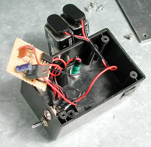
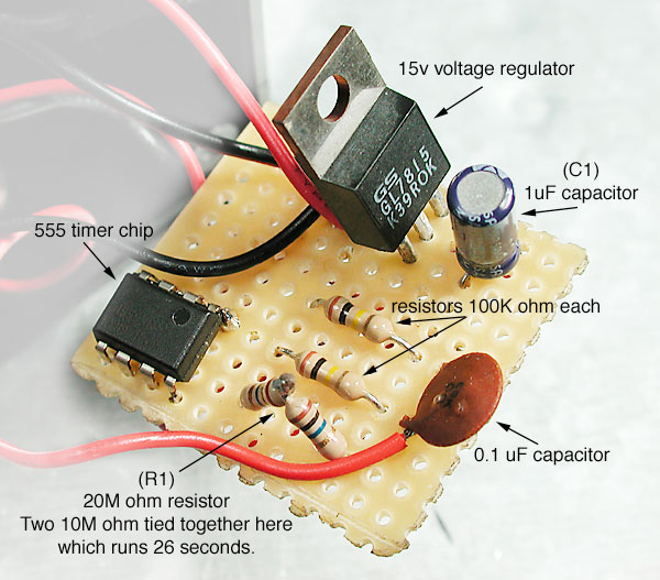
Batteries are required to power your fan in the field which can be cumbersome and expensive. An on/off switch of some type will help conserve batteries. A simple momentary push button switch may be the most elegant solution as a strong fan only needs to be turned on for a few seconds at a time. Rechargeable NiMh batteries can be used to soften the financial blow caused when the fan is accidentally left on. Multiple cells can be wired in series to achieve the required voltage. A typical high quality setup would be 8 AA cells with a momentary switch. Other more expensive battery options are 12v NiMh clusters used in RC cars/planes and cordless drills. The fan controller shown here uses (2) 9v cells to keep the controller small and lightweight and a voltage regulator to control the current. The controller also features a timer circuit which automatically shuts the fan off.

This timer is a monostable circuit which uses the venerable 555 timer chip. The 555 can only handle 15v so the power must be stepped down from 18v before entering the circuit. The duration of the timer depends on the values of (C1) and (R1) in the following examples. The parts shown here give a calculated run time of 22 seconds. Parts include: 2"x3"x1.5" project box, momentary pushbutton switch (special double pole 'DP' switch), LED w/resistor, 1/8" plug for fan (optional), circuit board, 555 timer, 15v voltage regulator, 0.1uF (micro farad) capacitor, 1uF capacitor (C1), (2) 100k ohm resistors, 20M ohm resistor (R1), 30 ohm resistor, (2) 12vdc 1A reed relays, (2) 9v battery connectors and (2) 9v batteries. Tools include a small soldering iron, thin solder, thin jumper wire and safety glasses.

fan-controlbox
fan-controlpartsonboard.jpg

The voltage regulator tames the batteries to a steady 15v and the timer circuit eats up about 1.6v more. Typically 13.4v of current is supplied at the fan producing strong air flow from the slightly overclocked fan. The 555 chip usually has a marking near pin #1, in this case it's a small circle. The 1uF cap (C1) shown here was salvaged from and old television/target to save a trip to the electronics store. This image does not show the additional 2 reed relays and 30 ohm resistor needed to fix a problem with unintentional battery drain. These components are shown in the schematic below.

This circuit was completed using jumper wires to connect the components. A clean soldering iron with a small tip helps with assembly. Avoid cold solders by heating all surfaces evenly. Small components heat up quickly and can be damaged if overcooked. Plan your solders then get in and get out. A printed type board with metal cells may also be used to streamline the connections and reduce jumper wires. Circuit board may be cut into shape by scoring with a razor then breaking by hand.

fan-controljumpers.jpg
fan-controlschematic.gif

Adjusting the values of (C1) and (R1) changes the duration of the timer. It is possible to substitute (R1) for a potentiometer to provide stepless time adjustments. This example uses (C1)=1uF and (R1)=20M ohm and times for 26 seconds although calculations say it should time for 22 seconds. Change the value of (R1) to 10M ohm to set the timer for about 12 seconds or 5M ohm for about 5 seconds. An online 555 timer calculator and the original schematic can be found at this link.

This is the revised schematic for the fan controller circuit wich eliminates the problem of unintentional battery drain. It uses two reed relays to isolate the timer circuit from the power source. The relays are small enough to fit inside the pictured project box alongside the batteries and the additional resistor will fit on the main board. It is also possible to use smaller switching components like transistors in place of the relays. This circuit uses a double pole (DP) switch which triggers the two separate circuits at the same time providing 12v at the fan. The toggle style power shutoff switch has been eliminated from the design but is easy to add next to the battery if desired. Large fans running at 12v can easily vent or mix in 2-3 seconds, 26 seconds is a little overkill. This circuit features a bit of circuit protection so crossing your output wires on accident shouldn't cause any harm.


back